Yamaha YZF-R125 Service Manual: Checking the switches
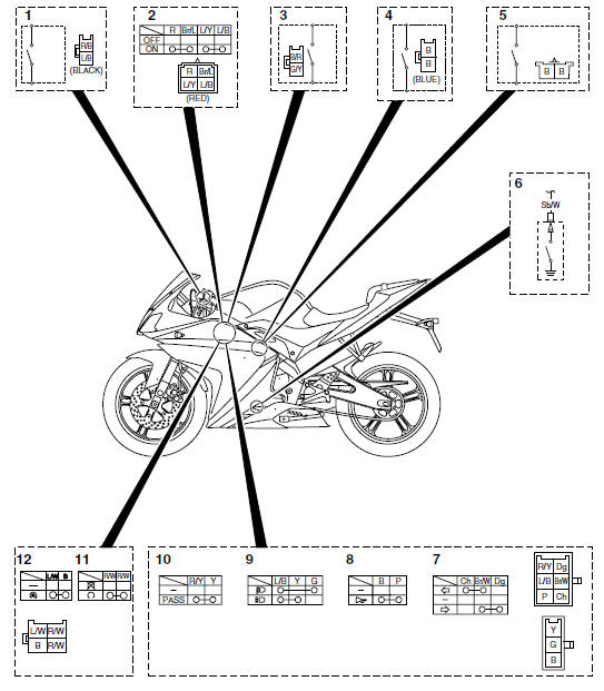
1. Clutch switch
2. Main switch
3. Front brake light switch
4. Sidestand switch
5. Rear brake light switch
6. Neutral switch
7. Turn signal switch
8. Horn switch
9. Dimmer switch
10.Pass switch
11.Engine stop switch
12.Start switch
Check each switch for continuity with the pocket tester. If the continuity reading is incorrect, check the wiring connections and, if necessary, replace the switch.
| CAUTION: Never insert the tester probes into the
coupler terminal slots "a". Always insert the probes from
the opposite end of the coupler, taking care not to loosen or damage the
leads. |
NOTE:
- Before checking for continuity, set the pocket tester to "0" and to the " × 1" range.
- When checking for continuity, switch back and forth between the switch positions a few times.
The switches and their terminal connections are illustrated as in the following example of the main switch.
The switch positions "a" are shown in the far left column and the switch lead colors "b" are shown in the top row.
The continuity (i. e., a closed circuit) between switch terminals at a given
switch position is indicated by
"  ". There is continuity between
red and brown/blue, and blue/yellow and blue/black when the
switch is set to "ON".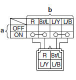
 Electrical components
1. Main switch
2. Clutch switch
3. Front brake light switch
4. Ignition coil
5. Throttle body sensor assembly (intake air
pressure sensor, intake air temperature
sensor, throttle position se ...
 Checking the bulbs and bulb sockets
NOTE:
Do not check any of the lights that use LEDs.
Check each bulb and bulb socket for damage or
wear, proper connections, and also for continuity
between the terminals.
Damage/wear Repa ...
Other materials:
Incorrect engine idling speed
Engine
1. Cylinder and cylinder head
Incorrect valve clearance
Damaged valve train components
2. Air filter
Clogged air filter element
Fuel system
1. Throttle body
Damaged or loose throttle body joint
Improperly adjusted engine idling speed (idle
adjusting screw)
Improper ...
Front wheel
To remove the front wheel
WARNING
To avoid injury, securely support the
vehicle so there is no danger of it
falling over.
Loosen the front wheel axle pinch
bolt, then the wheel axle and the
brake caliper bolts.
Front wheel axle pinch bolt
Lift the front wheel of ...
Checking the lean angle sensor
1. Remove:
Lean angle sensor
2. Check:
Lean angle sensor output voltage
Out of specification Replace.
a. Connect the lean angle sensor to the wire
harness.
b. Connect the pocket tester (DC 20 V) to the
lean angle sensor coupler as shown.
Positive tester probe
yellow/green "1"
Neg ...