
Yamaha YZF-R125 Service Manual: Adjusting the front wheel static balance
NOTE:
- After replacing the tire, wheel or both, the front wheel static balance should be adjusted.
- Adjust the front wheel static balance with the brake discs installed.
1. Remove:
- Balancing weight(s)
2. Find:
- Front wheel's heavy spot
NOTE:
Place the front wheel on a suitable balancing stand.
a. Spin the front wheel.
b. When the front wheel stops, put an "X1" mark at the bottom of the wheel.
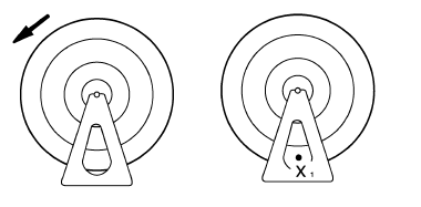
c. Turn the front wheel 90 so that the "X1" mark is positioned as shown.
d. Release the front wheel.
e. When the wheel stops, put an "X2" mark at the bottom of the wheel.
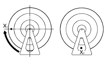
f. Repeat steps (c) through (e) several times until all the marks come to rest at the same spot.
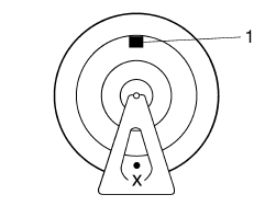
g. The spot where all the marks come to rest is the front wheel's heavy spot "X".
3. Adjust:
- Front wheel static balance
a. Install a balancing weight "1" onto the rim exactly opposite the heavy spot "X".
NOTE:
Start with the lightest weight.
b. Turn the front wheel 90 so that the heavy
spot is positioned as shown.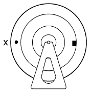
c. If the heavy spot does not stay in that position, install a heavier weight.
d. Repeat steps (b) and (c) until the front wheel is balanced.
4. Check:
- Front wheel static balance
a. Turn the front wheel and make sure it stays at
each position shown.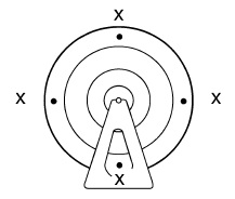
b. If the front wheel does not remain stationary at all of the positions, rebalance it.
 Assembling the front wheel
1. Install:
Wheel bearings
Oil seal
a. Install the new wheel bearings and oil seal in
the reverse order of disassembly.
CAUTION:Do not contact the wheel bearing inner
race
" ...
 Installing the front wheel (disc)
1. Install:
Front brake disc
NOTE:
Be sure to install the front brake disc with the
arrow mark "a" on the disc facing out.
Tighten the brake disc bolts in stages and in a
crisscross p ...
Other materials:
Checking and adjusting the steering head
1. Stand the vehicle on a level surface
WARNINGSecurely support the vehicle so that there
is
no danger of it falling over.
NOTE:
Place the vehicle on a suitable stand so that the
front wheel is elevated.
2. Check:
Steering head
Grasp the bottom of the front fork legs an ...
Checking the bulbs and bulb sockets
NOTE:
Do not check any of the lights that use LEDs.
Check each bulb and bulb socket for damage or
wear, proper connections, and also for continuity
between the terminals.
Damage/wear Repair or replace
the bulb,
bulb socket or both.
Improperly connected Properly
connect.
No c ...
Loading
Adding accessories or cargo to your
motorcycle can adversely affect stability
and handling if the weight distribution
of the motorcycle is changed. To avoid
the possibility of an accident, use extreme
caution when adding cargo or
accessories to your motorcycle. Use
extra care when ridi ...