Yamaha YZF-R125 Service Manual: Outline of the fi system
The main function of a fuel supply system is to provide fuel to the combustion chamber at the optimum air-fuel ratio in accordance with the engine operating conditions and the atmospheric temperature. In the conventional carburetor system, the air-fuel ratio of the mixture that is supplied to the combustion chamber is created by the volume of the intake air and the fuel that is metered by the jet used in the respective carburetor.
Despite the same volume of intake air, the fuel volume requirement varies by the engine operating conditions, such as acceleration, deceleration, or operating under a heavy load. Carburetors that meter the fuel through the use of jets have been provided with various auxiliary devices, so that an optimum airfuel ratio can be achieved to accommodate the constant changes in the operating conditions of the engine.
As the requirements for the engine to deliver more performance and cleaner exhaust gases increase, it becomes necessary to control the air-fuel ratio in a more precise and finely tuned manner. To accommodate this need, this model has adopted an electronically controlled fuel injection (FI) system, in place of the conventional carburetor system. This system can achieve an optimum air-fuel ratio required by the engine at all times by using a microprocessor that regulates the fuel injection volume according to the engine operating conditions detected by various sensors.
The adoption of the FI system has resulted in a highly precise fuel supply, improved engine response, better fuel economy, and reduced exhaust emissions.
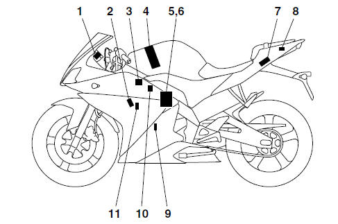
- Engine trouble warning light
- Spark plug
- Ignition coil
- Fuel pump
- FID (fast idle solenoid)
- Throttle body sensor assembly (consisting of throttle position sensor, intake air pressure sensor, intake air temperature sensor)
- ECU (engine control unit)
- Lean angle sensor
- Crankshaft position sensor
- Fuel injector
- Coolant temperature sensor
 Features
...
 Fi system
The fuel pump delivers fuel to the fuel injector via the fuel filter. The
pressure regulator maintains the
fuel pressure that is applied to the fuel injector at only 250 kPa (2.50 kg/cm²,
36 ...
Other materials:
Removing the valves
The following procedure applies to all of the
valves and related components.
NOTE:
Before removing the internal parts of the cylinder
head (e.g., valves, valve springs, valve seats),
make sure the valves properly seal.
1. Check:
Valve sealing
Leakage at the valve seat Check
the valve
...
Checking the camshaft sprocket and timing chain guide
1. Check:
Camshaft sprocket
More than 1/4 tooth wear "a" Replace
the
camshaft sprocket, timing chain and crankshaft
as a set.
a. 1/4 tooth
b. Correct
1. Timing chain roller
2. Camshaft sprocket
2. Check:
Timing chain guide (exhaust side)
Damage/wear Replace.
...
Installing the primary drive gear and balancer gears
1. Install:
Balancer driven gear "1"
Lock washer
Balancer drive gear "2"
Primary drive gear
Washer "3"
Balancer driven gear nut
Primary drive gear nut
NOTE:
Align the punch mark "a" in the balancer drive
gear "2" with the punch mark "b" in the balancer
driven gear "1".
...