Yamaha YZF-R125 Service Manual: Installing the rear brake master cylinder
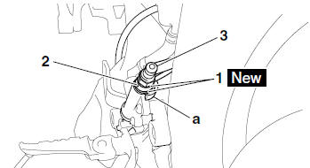
1. Install:
- Copper washers "1"

- Brake hose "2"
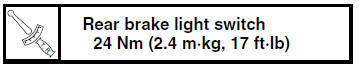
- Rear brake light switch "3"
| WARNING Proper brake hose routing is essential to insure safe vehicle operation. Refer to "CABLE ROUTING" on page 2-33. |
| CAUTION: When installing the brake hose onto the brake master cylinder, make sure the brake pipe touches the projection "a" as shown. |
2. Fill:
- Brake fluid reservoir
(with the specified amount of the recommended
brake fluid)
WARNING
|
| CAUTION: Brake fluid may damage painted surfaces and plastic parts. Therefore, always clean up any spilt brake fluid immediately. |
3. Bleed:
- Brake system Refer to "BLEEDING THE HYDRAULIC BRAKE SYSTEM" on page 3-20.
4. Check:
- Brake fluid level
Below the minimum level mark "a"

Add the recommended brake fluid to the proper level.Refer to "CHECKING THE BRAKE FLUID LEVEL" on page 3-18.
5. Check:
- Brake pedal operation
Soft or spongy feeling
 Bleed
Bleed
the brake system.Refer to "BLEEDING THE HYDRAULIC BRAKE SYSTEM" on page 3-20.
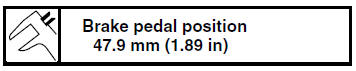
6. Adjust:
- Brake pedal position
Refer to "ADJUSTING THE REAR DISC
BRAKE" on page 3-18.
 Assembling the rear brake master cylinder
WARNING
Before installation, all internal brake components
should be cleaned and lubricated
with clean or new brake fluid.
Never use solvents on internal brake components.
...
 Handlebars
...
Other materials:
Checking the shift drum assembly
1. Check:
Shift drum groove
Damage/scratches/wear Replace
the shift
drum assembly.
Shift drum segment "1"
Damage/wear Replace the
shift drum assembly.
Shift drum bearing "2"
Damage/pitting Replace the
shift drum assembly.
...
Checking the transmission
1. Measure:
Main axle runout
(with a centering device and dial gauge "1")
Out of specification Replace
the main axle.
2. Measure:
Drive axle runout
(with a centering device and dial gauge "1")
Out of specification Replace
the drive axle.
3. Check:
Transmiss ...
Removing the crankshaft
1. Remove:
Crankshaft "1"
NOTE:
Remove the crankshaft with the crankcase
separating tool "2".
Make sure the crankcase separating tool is
centered over the crankshaft.
CAUTION:
To protect the end of the crankshaft, place
an appropriate sized socket between the
c ...