Yamaha YZF-R125 Service Manual: Installing the valves
The following procedure applies to all of the valves and related components.
1. Deburr:
- Valve stem end (with an oil stone)
2. Lubricate:
- Valve stem "1"
- Valve stem seal "2"

(with the recommended lubricant)
3. Install:
- Lower spring seat "1"
- Valve stem seal "2"

- Valve "3"
- Valve spring "4"
- Upper spring seat "5" (into the cylinder head)
NOTE:
- Make sure each valve is installed in its original place.
- Install the valve springs with the larger pitch "a" facing up.
b. Smaller pitch
4. Install:
- Valve cotters "1"
NOTE:
Install the valve cotters by compressing the
valve spring with the valve spring compressor
and the valve spring compressor attachment "2".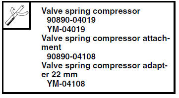
5. To secure the valve cotters onto the valve stem, lightly tap the valve tip with a soft-face hammer.
| CAUTION: Hitting the valve tip with excessive force could damage the valve. |
 Checking the valve springs
The following procedure applies to all of the
valve springs.
1. Measure:
Valve spring free length "a"
Out of specification Replace the valve
spring.
2. Measure:
Compressed valve ...

Other materials:
Checking the front brake lever free play
Checking the front brake lever free play
Brake lever free play
The brake lever free play should measure
2.0-5.0 mm (0.08-0.20 in) as
shown. Periodically check the brake lever
free play and, if necessary, have a
Yamaha dealer check the brake system.
WARNING
An incorrect brake le ...
Circuit diagram
2. Crankshaft position sensor
4. Main fuse
5. Main switch
6. Radiator fan motor fuse
8. Sidestand switch
9. Battery
17.Engine stop switch
19.Intake air pressure sensor
20.Intake air temperature sensor
21.Throttle position sensor
22.Coolant temperature sensor
23.Lean angle sensor
24.S ...
Checking the fid (fast idle solenoid)
1. Disconnect:
FID (fast idle solenoid) coupler
2. Check:
FID (fast idle solenoid) resistance
a. Disconnect the FID (fast idle solenoid) coupler
from the FID.
b. Connect the pocket tester ( × 10)
to the terminals
of the FID (fast idle solenoid).
Positive tester probe ...