Yamaha YZF-R125 Service Manual: Circuit diagram
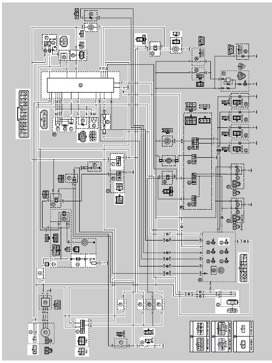
2. Crankshaft position sensor
4. Main fuse
5. Main switch
6. Radiator fan motor fuse
8. Sidestand switch
9. Battery
17.Engine stop switch
19.Intake air pressure sensor
20.Intake air temperature sensor
21.Throttle position sensor
22.Coolant temperature sensor
23.Lean angle sensor
24.Self-diagnosis signal connector
25.ECU (engine control unit)
26.Ignition coil
27.Spark plug
28.FID (fast idle solenoid)
29.Fuel injector
30.Fuel pump
32.Radiator fan motor relay
33.Radiator fan motor
63.Engine trouble warning light
64.Ignition fuse
66.Signaling system fuse
67.Speed sensor

 Ecu self-diagnostic function
The ECU is equipped with a self-diagnostic function in order to ensure that
the fuel injection system is
operating normally. If this function detects a malfunction in the system, it
immediately o ...
Other materials:
Shifting
Shifting
Shift pedal
Neutral position
Shifting gears lets you control the
amount of engine power available for
starting off, accelerating, climbing hills,
etc.
The gear positions are shown in the illustration.
TIP
To shift the transmission into the neutral
position, press the ...
Owner's tool kit
Owner's tool kit
Owner's tool kit
Engine oil drain attachment
The owner's tool kit is located under the
rider seat.
The service information included in this
manual and the tools provided in the
owner's tool kit are intended to assist
you in the performance of preventive
maint ...
Faulty clutch
Clutch slips
1. Clutch
Improperly assembled clutch
Improperly adjusted clutch cable
Loose or fatigued clutch spring
Worn friction plate
Worn clutch plate
2. Engine oil
Incorrect oil level
Incorrect oil viscosity (low)
Deteriorated oil
Clutch drags
1. Clutch
Unevenly t ...