Yamaha YZF-R125 Service Manual: Cooling system diagrams
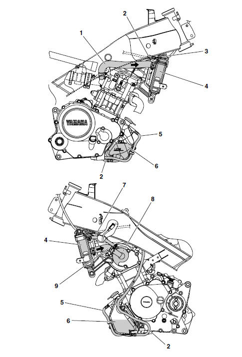
- Radiator inlet hose
- Coolant reservoir hose
- Radiator cap
- Radiator
- Coolant reservoir breather hose
- Coolant reservoir
- Water pump breather hose
- Water pump
- Radiator outlet hose
 Lubrication diagrams
Clutch push lever
Main axle
Drive axle
Crankshaft
Oil filter
Oil pump assembly
Oil strainer
To cylinder head
Camshaft
Crankshaft
Main axle
Drive axle
...
 Cable routing
Front brake light switch lead
Right handlebar switch lead
Throttle cable
Main switch
Clutch cable
Clutch switch lead
Left handlebar switch lead
Sub-wire harness
Horn
Speed sen ...
Other materials:
Assembling the water pump
1. Install:
Water pump seal "1"
(into the water pump housing "2")
CAUTION:Never lubricate the water pump seal
surface
with oil or grease.
NOTE:
Install the water pump seal with the special
tools.
Install the water pump seal with the special
tools to the specifi ...
Outline of the fi system
The main function of a fuel supply system is to provide fuel to the
combustion chamber at the optimum
air-fuel ratio in accordance with the engine operating conditions and the
atmospheric temperature. In
the conventional carburetor system, the air-fuel ratio of the mixture that is
supplied t ...
General maintenance and lubrication chart
TIP
The air filter needs more frequent service if you are riding in
unusually wet or dusty areas.
Hydraulic brake service
Regularly check and, if necessary, correct the brake fluid level.
Every two years change the brake fluid.
Replace the brake hoses every four ye ...