
Yamaha YZF-R125 Service Manual: Cable routing
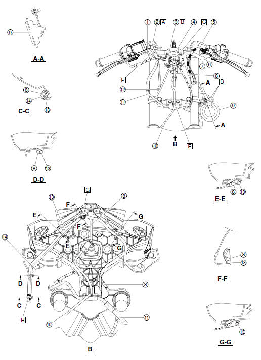
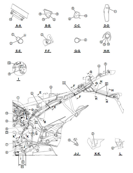
- Front brake light switch lead
- Right handlebar switch lead
- Throttle cable
- Main switch
- Clutch cable
- Clutch switch lead
- Left handlebar switch lead
- Sub-wire harness
- Horn
- Speed sensor lead
- Front brake hose
- Main switch lead
- Left headlight assembly lead
- Right headlight assembly lead
A. Route the right handlebar switch lead to the rear the front brake hose.
B. Route the throttle cable in front of the front brake light switch lead.
C. Pass the throttle cable through the guide.
D. Connect the horn connectors to the horn terminals as shown in the illustration.
E. Secure the plastic locking tie by inserting the projection on the tie into the hole in the front brake pipe bracket, and then fasten the speed sensor lead with the tie.
F. Pass the front brake light switch lead between the throttle cable and the front brake hose.
G. Fasten the left headlight assembly lead and subwire harness to the right headlight body with a plastic locking tie as shown in the illustration, making sure to align the white tape on the lead and harness with the tie.
H. Fasten the left headlight assembly lead, right headlight assembly lead, and sub-wire harness with a plastic locking tie, making sure to align the white tape on the leads and harness with the tie.
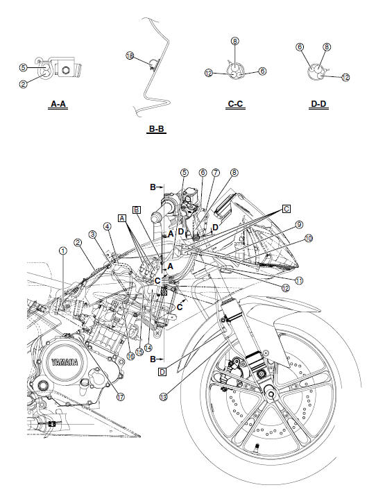
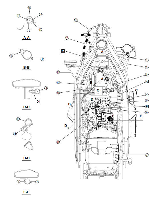
- Throttle body
- Wire harness
- Ignition coil
- Spark plug lead
- Sub-wire harness
- Front brake light switch lead
- Throttle cable
- Right handlebar switch lead
- Right headlight assembly lead
- Left headlight assembly lead
- Front brake hose
- Main switch lead
- Speed sensor lead
- Radiator inlet hose
- Radiator fan motor lead
- Wire harness (to coolant temperature sensor)
- Starter motor
- Front turn signal light lead
A. Cover the sub-wire harness couplers with the coupler cover.
B. Fasten the wire harness and sub-wire harness to the guide with a plastic locking tie.
C. After connecting the wire harness to the left and right headlight assembly leads, cover the couplers with the coupler cover, and then fasten a plastic locking tie around the end of the cover as shown in the illustration.
D. Fasten the grommet on the speed sensor lead with the holder.
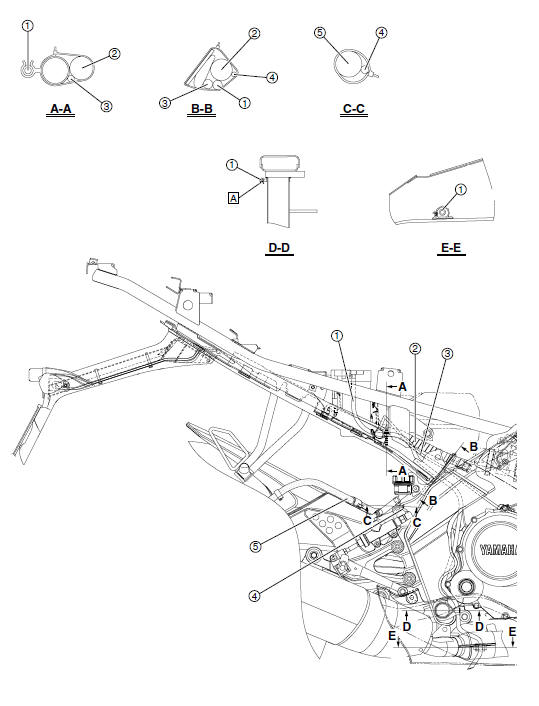
- Battery breather hose
- Wire harness
- Starter motor lead
- Rear brake light switch lead
- Rear brake hose
A. Fasten the battery breather hose with the holder.
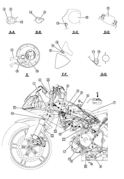
- Front brake hose
- Throttle cable
- Left handlebar switch lead
- Clutch cable
- Wire harness (to horn)
- Ignition coil
- Air filter case silencer hose
- Sidestand switch lead
- Coolant reservoir hose
- Fuel tank breather hose
- Coolant reservoir breather hose
- Front left turn signal light coupler
- Speed sensor lead
- Wire harness (to clutch switch)
- Front left turn signal light lead
- Horn
- Fuel hose
- Fuel pump lead
- Fuel sender lead
A. Fasten the left handlebar switch lead, wire harness (to clutch switch), and clutch cable with a plastic locking tie, making sure to align the white tape on the leads and cable with the tie.
B. Fasten the sidestand switch lead, coolant reservoir hose, and fuel tank breather hose with the plastic clamp.
C. Fasten the sidestand switch lead, coolant reservoir hose, and fuel tank breather hose to the left side cowling bracket with the plastic clamp.
D. Fasten the wire harness (to clutch switch) and left handlebar switch lead to the left radiator bracket with a plastic locking tie, making sure to align the white tape on the harness and lead with the tie, and then route the harness and lead to the inside of the clutch cable guide.
E. Fasten the grommet on the front brake hose with the holder.
F. Route the throttle cable to the inside of the radiator bracket and pass the cable through the guide on the radiator cover.
- Air filter case silencer hose
- Wire harness
- Battery
- Lean angle sensor
- Tail/brake light lead
- Sidestand switch lead
- Neutral switch
- Crankshaft position sensor/stator coil lead
- Negative battery lead
- Rectifier/regulator
- Ground lead terminal
- Rear right turn signal light lead
- License plate light lead
- Rear left turn signal light lead
- Wire harness (to neutral switch)
A. Fasten the wire harness at the white tape with a plastic locking tie.
B. Fasten the license plate light lead, rear left turn signal light lead, and rear right turn signal light lead to the rear fender stay with plastic locking ties, making sure to align the white tape on the leads with the ties.
C. Route the fuel tank breather hose and coolant reservoir breather hose so that the end of each hose is positioned further rearward than the sidestand pivoting point as shown in the illustration.
D. Pass the wire harness (to neutral switch) through the guide on the left crankcase, making sure to align the white tape on the harness with the guide as shown in the illustration.
E. 50-90 F. 100 mm (3.94 in) G. Fasten the sidestand switch lead at the white tape with the holder.
H. 65 mm (2.56 in)
- Coolant reservoir hose
- Radiator inlet hose
- Spark plug lead
- Wire harness
- FID (fast idle solenoid) lead
- Fuel injector lead
- Rear brake light switch lead
- Throttle body sensor assembly
- Ignition coil leads
- Air filter case silencer hose
- Wire harness (to horn)
- Clutch cable
- Throttle cable
- Wire harness (to left handlebar switch)
- Front brake light switch lead
- Right handlebar switch lead
- Main switch lead
- Cylinder head breather hose
A. Fasten the wire harness with the plastic locking tie.
B. Fasten the fuel injector lead and FID (fast idle solenoid) lead with a plastic locking tie.
C. Pass the clutch cable through the guide.
D. Secure the plastic locking tie by inserting the projection on the tie into the hole in the frame.
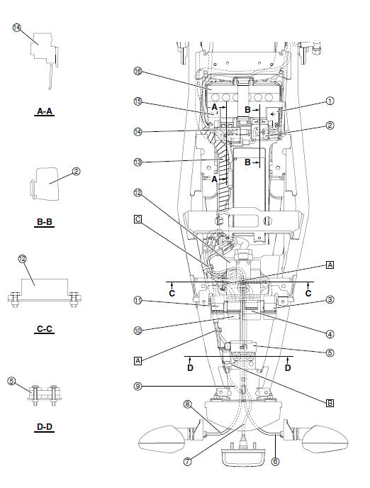
- Positive battery lead
- Starter relay
- Radiator fan motor relay
- Turn signal relay
- Lean angle sensor
- Rear right turn signal light lead
- License plate light lead
- Rear left turn signal light lead
- Tail/brake light lead
- Starting circuit cut-off relay
- Headlight relay
- ECU (engine control unit)
- Wire harness
- Fuse box
- Negative battery lead
- Battery
A. Fasten the wire harness with a plastic locking tie.
B. Fasten the tail/brake light coupler to the frame with a plastic locking tie.
C. Fasten the license plate light lead, rear right turn signal light lead, rear left turn signal light lead, and wire harness with a plastic locking tie.
 Cooling system diagrams
Radiator inlet hose
Coolant reservoir hose
Radiator cap
Radiator
Coolant reservoir breather hose
Coolant reservoir
Water pump breather hose
Water pump
Radiator outlet hose
...

Other materials:
Removing the swingarm
1. Stand the vehicle on a level surface.
WARNINGSecurely support the vehicle
so that there is
no danger of it falling over.
NOTE:
Place the vehicle on a suitable stand so that the
rear wheel is elevated.
2. Measure:
Swingarm side play
Swingarm vertical movement
a. Me ...
Rear wheel
To remove the rear wheel
WARNING
To avoid injury, securely support the
vehicle so there is no danger of it
falling over.
Loosen the axle nut.
Axle nut
Drive chain slack adjusting bolt
Locknut
Brake caliper
Lift the rear wheel off the ground
according to the pr ...
Troubleshooting
Although Yamaha motorcycles receive
a thorough inspection before shipment
from the factory, trouble may occur during
operation. Any problem in the fuel,
compression, or ignition systems, for
example, can cause poor starting and
loss of power.
The following troubleshooting charts
repre ...