Yamaha YZF-R125 Service Manual: Checking the valve seats
The following procedure applies to all of the valves and valve seats.
1. Eliminate:
- Carbon deposits (from the valve face and valve seat)
2. Check:
- Valve seat
Pitting/wear
 Replace the
cylinder head.
3. Measure:
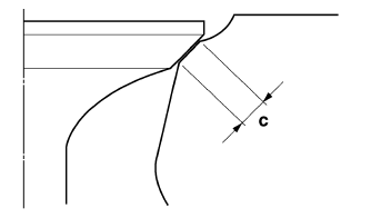
- Valve seat width C "a"
Out of specification
 Replace
the cylinder head.
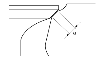
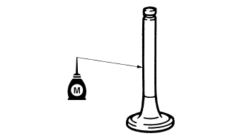
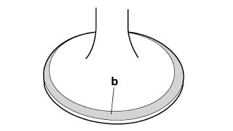
a. Apply Mechanic's blueing dye (Dykem) "b" onto the valve face.
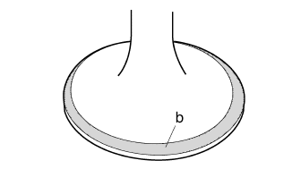
b. Install the valve into the cylinder head.
c. Press the valve through the valve guide and onto the valve seat to make a clear impression.
d. Measure the valve seat width.
NOTE:
Where the valve seat and valve face contacted one another, the blueing will have been removed.
4. Lap:
- Valve face
- Valve seat
NOTE:
After replacing the cylinder head or replacing the valve and valve guide, the valve seat and valve face should be lapped.
a. Apply a coarse lapping compound "a" to the valve face.
| CAUTION: Do not let the lapping compound enter the gap between the valve stem and the valve guide. |
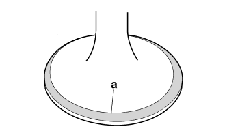
b. Apply molybdenum disulfide oil onto the valve stem.
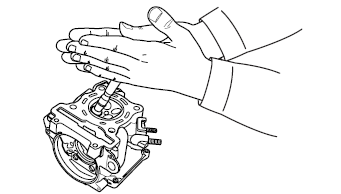
c. Install the valve into the cylinder head.
d. Turn the valve until the valve face and valve seat are evenly polished, then clean off all of the lapping compound.
NOTE:
For the best lapping results, lightly tap the valve seat while rotating the valve back and forth between your hands.
e. Apply a fine lapping compound to the valve face and repeat the above steps.
f. After every lapping procedure, be sure to clean off all of the lapping compound from the valve face and valve seat.
g. Apply Mechanic's blueing dye (Dykem) "b" onto the valve face.
h. Install the valve into the cylinder head.
i. Press the valve through the valve guide and onto the valve seat to make a clear impression.
j. Measure the valve seat width "c" again. If the valve seat width is out of specification, reface and lap the valve seat.
 Checking the valves and valve guides
The following procedure applies to all of the
valves and valve guides.
1. Measure:
Valve-stem-to-valve-guide clearance
Out of specification Replace the
valve
guide.
Valve-stem-to-valve ...
 Checking the valve springs
The following procedure applies to all of the
valve springs.
1. Measure:
Valve spring free length "a"
Out of specification Replace the valve
spring.
2. Measure:
Compressed valve ...
Other materials:
Checking the fid (fast idle solenoid)
1. Disconnect:
FID (fast idle solenoid) coupler
2. Check:
FID (fast idle solenoid) resistance
a. Disconnect the FID (fast idle solenoid) coupler
from the FID.
b. Connect the pocket tester ( × 10)
to the terminals
of the FID (fast idle solenoid).
Positive tester probe ...
Starting failures
Engine
1. Cylinder and cylinder head
- Loose spark plug
- Loose cylinder head or cylinder
- Damaged cylinder head gasket
- Damaged cylinder gasket
- Worn or damaged cylinder
- Incorrect valve clearance
- Improperly sealed valve
- Incorrect valve-to-valve-seat contact
- Incorrect valve timi ...
Battery
A poorly maintained battery will corrode
and discharge quickly. The electrolyte
level, battery lead connections and
breather hose routing should be
checked before each ride and at the intervals
specified in the periodic maintenance
and lubrication chart.
WARNING
Electrolyte is pois ...