Yamaha YZF-R125 Service Manual: Checking the valves and valve guides
The following procedure applies to all of the valves and valve guides.
1. Measure:
- Valve-stem-to-valve-guide clearance
Out of specification
 Replace the
valve guide.
Valve-stem-to-valve-guide clearance =
Valve guide inside diameter "a" -
Valve stem diameter "b" 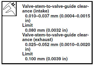
2. Replace:
- Valve guide
NOTE:
To ease valve guide removal and installation, and to maintain the correct fit, heat the cylinder head to 100 C (212 F) in an oven.
a. Remove the valve guide with the valve guide remover "1".
b. Install the new valve guide with the valve
guide installer "2" and valve guide remover
"1". 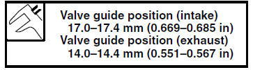
a. Valve guide position
c. After installing the valve guide, bore the valve guide with the valve guide reamer "3" to obtain the proper valve-stem-to-valve-guide clearance.
NOTE:
After replacing the valve guide, reface the valve
seat. 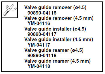
3. Eliminate:
- Carbon deposits (from the valve face and valve seat)
4. Check:
- Valve face
Pitting/wear
 Grind the valve
face. - Valve stem end
Mushroom shape or diameter larger than the
body of the valve stem
 Replace
the valve.
5. Measure:
- Valve margin thickness D "a"
Out of specification Replace
the valve.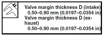
6. Measure:
- Valve stem runout
Out of specification Replace
the valve.
NOTE:
- When installing a new valve, always replace the valve guide.
- If the valve is removed or replaced, always replace
the valve stem seal.

 Removing the valves
The following procedure applies to all of the
valves and related components.
NOTE:
Before removing the internal parts of the cylinder
head (e.g., valves, valve springs, valve seats),
make sure th ...
 Checking the valve seats
The following procedure applies to all of the
valves and valve seats.
1. Eliminate:
Carbon deposits
(from the valve face and valve seat)
2. Check:
Valve seat
Pitting/wear Replace the ...
Other materials:
Circuit diagram
2. Crankshaft position sensor
4. Main fuse
5. Main switch
6. Radiator fan motor fuse
8. Sidestand switch
9. Battery
17.Engine stop switch
19.Intake air pressure sensor
20.Intake air temperature sensor
21.Throttle position sensor
22.Coolant temperature sensor
23.Lean angle sensor
24.S ...
Throttle position sensor
1. Check:
Throttle position sensor
a. Connect the digital circuit tester to the terminals
of the throttle body sensor assembly
coupler as shown.
Positive tester probe →
gray/red terminal "1"
Negative tester probe →
gray/black terminal "2"
b. Measure the throttle pos ...
Owner's tool kit
Owner's tool kit
Owner's tool kit
Engine oil drain attachment
The owner's tool kit is located under the
rider seat.
The service information included in this
manual and the tools provided in the
owner's tool kit are intended to assist
you in the performance of preventive
maint ...