Yamaha YZF-R125 Service Manual: Checking the turn signal relay
1. Check:
Turn signal relay input voltage
Out of specification →The wiring circuit
from
the main switch to the turn signal relay coupler
is faulty and must be repaired.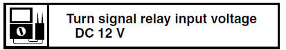
a. Connect the pocket tester (DC 20 V) to the
turn signal relay terminal as shown.
- Positive tester probe 
brown "1"
- Negative tester probe 
ground 
b. Set the main switch to "ON".
c. Measure the turn signal relay input voltage.
2. Check:
Turn signal relay output voltage
Out of specification Replace.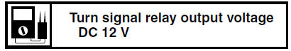
a. Connect the pocket tester (DC 20 V) to the
turn signal relay terminal as shown. 
Positive tester probe
brown/white "1"
Negative tester probe
ground
b. Set the main switch to "ON".
c. Measure the turn signal relay output voltage.
 Checking the relays
Check each switch for continuity with the pocket
tester. If the continuity reading is incorrect, replace
the relay.
1. Disconnect the relay from the wire harness.
2. Connect the pocket tester ( ...
 Checking the diode
1. Check:
Diode
Out of specification Replace.
NOTE:
The pocket tester or the analog pocket tester
readings are shown in the following table.
a. Disconnect the diode from the wire harness.
...
Other materials:
Checking the ignition timing
NOTE:
Prior to checking the ignition timing, check the
wiring connections of the entire ignition system.
Make sure all connections are tight and free of
corrosion.
1. Remove:
Rider seat
Left lower side cowling
Refer to "GENERAL CHASSIS" on page 4-1.
2. Remove:
Timing mark acces ...
Removing the swingarm
1. Stand the vehicle on a level surface.
WARNINGSecurely support the vehicle
so that there is
no danger of it falling over.
NOTE:
Place the vehicle on a suitable stand so that the
rear wheel is elevated.
2. Measure:
Swingarm side play
Swingarm vertical movement
a. Me ...
Checking the rectifier/regulator
1. Check:
Rectifier/regulator output voltage
Out of specification → Replace the
rectifier/
regulator.
a. Set the engine tachometer to the spark plug
lead.
b. Connect the pocket tester (DC 20 V) to the
rectifier/regulator coupler as shown.
Positive tester probe
red "1"
Negat ...