
Yamaha YZF-R125 Service Manual: Assembling the front fork legs
The following procedure applies to both of the front fork legs.
WARNING
|
NOTE:
When assembling the front fork leg, be sure to replace the following parts:
- Outer tube bushing
- Oil seal
- Dust seal
- Clip
Before assembling the front fork leg, make sure all of the components are clean.
1. Install:
- Damper rod
| CAUTION: Allow the damper rod to slide slowly down the inner tube until it protrudes from the bottom of the inner tube. Be careful not to damage the inner tube. |
2. Lubricate:
- Inner tube's outer surface

3. Tighten:
- Damper rod bolt "1"

NOTE:
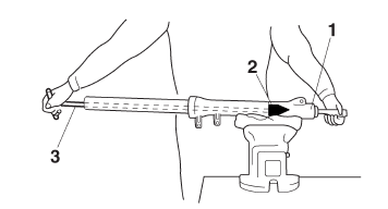
While holding the damper rod with the damper
rod holder "2" and T-handle "3", tighten the
damper rod bolt.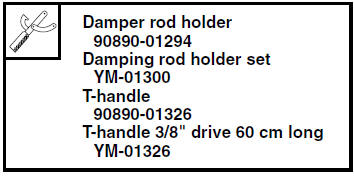
4. Install:
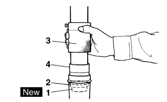
- Outer tube bushing "1"
- Washer "2"
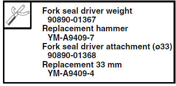
(with the fork seal driver weight "3" and fork
seal driver attachment "4")
5. Install:
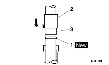
- Oil seal "1"

(with the fork seal driver weight "2" and fork seal driver attachment "3")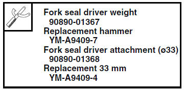
| CAUTION: Make sure the numbered side of the oil seal faces up. |
NOTE:
- Before installing the oil seal, lubricate its lips with lithium-soap-based grease.
- Lubricate the outer surface of the inner tube with fork oil.
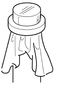
- Before installing the oil seal, cover the top of
the front fork leg with a plastic bag to protect
the oil seal during installation.
6. Install:
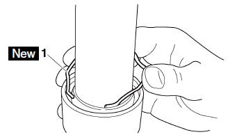
- Oil seal clip "1"
NOTE:
Adjust the oil seal clip so that it fits into the outer tube's groove.
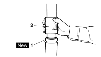
7. Install:
- Dust seal "1"

(with the fork seal driver weight "2")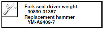
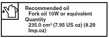
8. Fill:
- Front fork leg
(with the specified amount of the recommended
fork oil)
CAUTION:
|
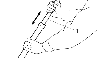
9. After filling the front fork leg, slowly stroke the inner tube "1" up and down (at least ten times) to distribute the fork oil.
NOTE:
Be sure to stroke the inner tube slowly because the fork oil may spurt out.
10.Before measuring the fork oil level, wait ten minutes until the oil has settled and the air bubbles have dispersed.
NOTE:
Be sure to bleed the front fork leg of any residual air.
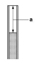
11.Measure:
Front fork leg oil level "a"
(from the top of the inner tube, with the inner
tube fully compressed and without the fork
spring)
Out of specification  Correct.
 12.Install:
- Fork spring "1"
NOTE:
Install the spring with the smaller pitch "a" facing
up.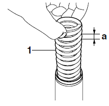
13.Install:
- O-ring

(to front fork cap) - Front fork cap
- Clip

NOTE:
- Before installing the front fork cap, lubricate its O-ring with grease.
- Insert the front fork cap into the inner tube, and then install the clip, making sure that the cap is securely held in place with the clip.
 Checking the front fork legs
The following procedure applies to both of the
front fork legs.
1. Check:
Inner tube
Outer tube
Bends/damage/scratches
Replace.
WARNINGDo not attempt to straighten a bent inner ...
 Installing the front fork legs
The following procedure applies to both of the
front fork legs.
1. Install:
Front fork leg
Temporarily tighten the upper and lower
bracket pinch bolts.
NOTE:
Make sure the inner tube end ...
Other materials:
Checking and lubricating the brake and shift pedals
Brake pedal
Brake pedal
Shift pedal
Shift pedal
The operation of the brake and shift
pedals should be checked before each
ride, and the pedal pivots should be lubricated
if necessary.
Recommended lubricant:Lithium-soap-based grease
...
Assembling the front brake caliper
WARNING
Before installation, all internal brake components
should be cleaned and lubricated
with clean or new brake fluid.
Never use solvents on internal brake components
as they will cause the brake caliper
dust seals and piston seals to swell and
distort.
...
Important manual information
Particularly important information is distinguished in this manual by the
following notations:
This is the safety alert symbol. It is used to alert you to potential personal
injury
hazards. Obey all safety messages that follow this symbol to avoid possible
injury
or death.
WARNING
...