Yamaha YZF-R125 Service Manual: Assembling the crankcase
1. Thoroughly clean all the gasket mating surfaces and crankcase mating surfaces.
2. Apply:
- Sealant
(onto the crankcase mating surfaces)
NOTE:
Do not allow any sealant to come into contact with the oil gallery.
3. Install:
- Right crankcase
NOTE:
Turn the shift drum segment "1" to the position shown in the illustration. In this position, the shift drum segment teeth will not contact the crankcase during crankcase installation.
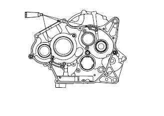
4. Install:
- Crankcase bolts
NOTE:
Tighten each bolt 1/4 of a turn at a time, in stages and in the proper sequence as shown.
- M6 × 70 mm : "7-9", "11"
- M6 × 55 mm : "14", "15"
- M6 × 45 mm : "1-5", "10"
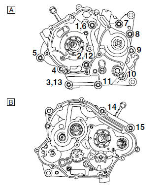
A. Left crankcase
B. Right crankcase
 Installing the bearing retainer
1. Install:
Bearing retainer "1"
NOTE:
Install the bearing retainer "1" with its "OUT"
mark "a" facing outward.
Apply locking agent (LOCTITE) to the
threads of the bearing retainer bo ...
 Crankshaft
...
Other materials:
Checking the rocker arms and rocker arm shafts
The following procedure applies to all of the
rocker arms and rocker arm shafts.
1. Check:
Rocker arm
Damage/wear Replace.
2. Check:
Rocker arm shaft
Blue discoloration/excessive wear/pitting/
scratches Replace or
check the lubrication
system.
3. Measure:
Rocke ...
Adjusting the exhaust gas volume
NOTE:
Be sure to set the CO density level to standard,
and then adjust the exhaust gas volume.
1. Remove:
Rider seat
Refer to "GENERAL CHASSIS" on page 4-1.
2. Set the main switch to "OFF".
3. Disconnect:
Self-diagnosis signal connector "1"
4. Connect:
FI diagnostic tool "2 ...
Electrical components
1. Main switch
2. Clutch switch
3. Front brake light switch
4. Ignition coil
5. Throttle body sensor assembly (intake air
pressure sensor, intake air temperature
sensor, throttle position sensor)
6. FID (fast idle solenoid)
7. Rectifier/regulator
8. Lean angle sensor
9. Starting circui ...