Yamaha YZF-R125 Service Manual: Replacing the rear brake pads
NOTE:
When replacing the brake pads, it is not necessary to disconnect the brake hose or disassemble the brake caliper.
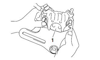
1. Remove:
- Brake pads
- Brake pad spring
NOTE:
To remove the inner brake pad "1", push down on the brake caliper bracket so that there is space to remove the brake pad.
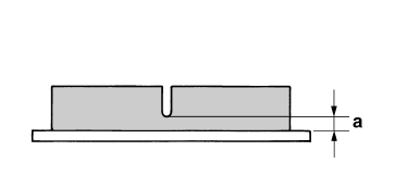
2. Measure:
Brake pad wear limit "a"
Out of specification → Replace the brake
pads as a set. 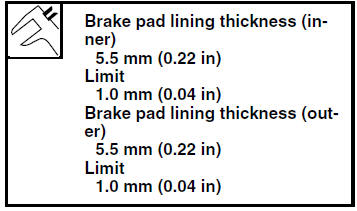
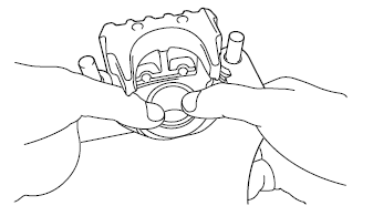
3. Install:
- Brake pad spring

- Brake pads

NOTE:
Always install new brake pads and a new brake pad spring as a set.
a. Connect a clear plastic hose tightly to the bleed screw. Put the other end of the hose into an open container.
b. Loosen the bleed screw and push the brake caliper piston into the brake caliper with your finger.
c. Tighten the bleed screw. 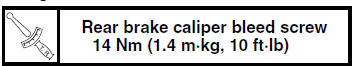
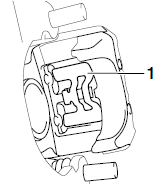
d. Install a new brake pad spring "1" and new brake pads.
NOTE:
Install the brake pad spring as shown.
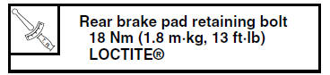
4. Install:
- Brake pad retaining bolts
- Brake caliper
5. Install:
- Rear wheel Refer to "REAR WHEEL" on page 4-12.
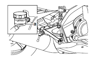
6. Check:
- Brake fluid level
Below the minimum level mark "a"
 Add the
recommended brake fluid to the proper level.Refer to "CHECKING THE BRAKE FLUID LEVEL" on page 3-18.
7. Check:
- Brake pedal operation
Soft or spongy feeling Bleed
the brake system.Refer to "BLEEDING THE HYDRAULIC BRAKE SYSTEM" on page 3-20.
 Checking the rear brake disc
1. Remove:
Rear wheel
Refer to "REAR WHEEL" on page 4-12.
2. Check:
Brake disc
Damage/galling → Replace.
3. Measure:
Brake disc deflection
Out of specification → Correc ...
 Removing the rear brake caliper
NOTE:
Before disassembling the brake caliper, drain
the brake fluid from the entire brake system.
1. Remove:
Union bolt "1"
Copper washers "2"
Brake hose "3"
NOTE:
Put the end of th ...
Other materials:
Assembling the crankcase
1. Thoroughly clean all the gasket mating surfaces
and crankcase mating surfaces.
2. Apply:
Sealant
(onto the crankcase mating surfaces)
NOTE:
Do not allow any sealant to come into contact
with the oil gallery.
3. Install:
Right crankcase
NOTE:
Turn the shift drum segment ...
Adjusting the brake pedal free play
Adjusting the brake pedal free play
Brake pedal free play
The brake pedal free play should measure
3.5-4.5 mm (0.14-0.18 in) as
shown. Periodically check the brake
pedal free play and, if necessary, have
a Yamaha dealer adjust it.
WARNING
An incorrect brake pedal free play
in ...
Checking the coolant temperature sensor
1. Remove:
Coolant temperature sensor
WARNING
Handle the coolant temperature sensor
with special care.
Never subject the coolant temperature sensor
to strong shocks. If the coolant temperature
sensor is dropped, replace it.
2. Check:
Coolant temper ...