Yamaha YZF-R125 Service Manual: Installing the piston and cylinder
1. Install:
- Top ring "1"
- 2nd ring "2"
- Oil ring expander "3"
- Lower oil ring rail "4"
- Upper oil ring rail "5"
NOTE:
Be sure to install the piston rings so that the manufacturer marks or numbers face up.
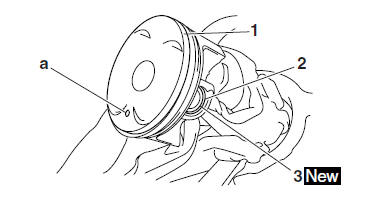
2. Install:
- Piston "1"
- Piston pin "2"
- Piston pin clips "3"

NOTE:
- Apply engine oil to the piston pin.
- Make sure the arrow mark "a" on the piston points towards the exhaust side of the cylinder.
- Before installing the piston pin clips, cover the crankcase opening with a clean rag to prevent the clips from falling into the crankcase.
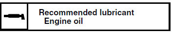
3. Lubricate:
- Piston
- Piston rings
- Cylinder
(with the recommended lubricant)
4. Offset:
- Piston ring end gaps
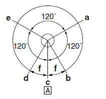
a. Top ring
b. Upper oil ring rail
c. Oil ring expander
d. Lower oil ring rail
e. 2nd ring
f. 20 mm (0.79 in)
A. Intake side
5. Install:
- Dowel pins
- Cylinder head gasket

- Cylinder "1"
NOTE:
- While compressing the piston rings with one hand, install the cylinder with the other hand.
- Pass the timing chain and timing chain guide (intake side) through the timing chain cavity.
 Checking the piston pin
1. Check:
Piston pin
Blue discoloration/grooves
Replace the
piston pin and then check the lubrication system.
2. Measure:
Piston pin outside diameter "a"
Out of specification ...

Other materials:
Genuine Yamaha Accessories
Choosing accessories for your vehicle
is an important decision. Genuine
Yamaha accessories, which are available
only from a Yamaha dealer, have
been designed, tested, and approved
by Yamaha for use on your vehicle.
Many companies with no connection to
Yamaha manufacture parts and access ...
Safe Riding
Perform the pre-operation checks each
time you use the vehicle to make sure it
is in safe operating condition. Failure to
inspect or maintain the vehicle properly
increases the possibility of an accident
or equipment damage. See page 4-1
for a list of pre-operation checks.
This motor ...
Owner's tool kit
Owner's tool kit
Owner's tool kit
Engine oil drain attachment
The owner's tool kit is located under the
rider seat.
The service information included in this
manual and the tools provided in the
owner's tool kit are intended to assist
you in the performance of preventive
maint ...