Yamaha YZF-R125 Service Manual: Circuit diagram
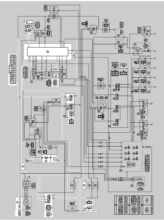
2. Crankshaft position sensor
4. Main fuse
5. Main switch
8. Sidestand switch
9. Battery
17.Engine stop switch
23.Lean angle sensor
25.ECU (engine control unit)
26.Ignition coil
27.Spark plug
64.Ignition fuse
 Ignition system
...
 Troubleshooting
The ignition system fails to operate (no spark or intermittent spark).
NOTE:
Before troubleshooting, remove the following part(s):
1. Seats
2. Fuel tank
3. Right side cover
4. Left side pan ...
Other materials:
Checking the diode
1. Check:
Diode
Out of specification Replace.
NOTE:
The pocket tester or the analog pocket tester
readings are shown in the following table.
a. Disconnect the diode from the wire harness.
b. Connect the pocket tester ( × 1)
to the diode
terminals as shown.
c. Check the diod ...
Checking the throttle body joint and air filter case joint
1. Remove:
Right lower side cowling
Left lower side cowling
Refer to "GENERAL CHASSIS" on page 4-1.
2. Check:
Throttle body joint "1"
Air filter case joint "2"
Cracks/damage Replace.
3. Install:
Right lower side cowling
Left lower side cowling
Refer to "GENERAL CHAS ...
Installing the clutch
1. Install:
Conical spring washer "1"
NOTE:
Install the conical spring washer as shown in the
illustration.
2. Install:
Clutch housing
Thrust washer "1"
NOTE:
Be sure to install the thrust washer so that its
sharp edge "a" is facing away from the clutch
boss.
3. Instal ...