Yamaha YZF-R125 Service Manual: Checking the steering head
1. Wash:
- Bearings
- Bearing races

2. Check:
- Bearings
- Bearing races Damage/pitting →Replace.
3. Replace:
- Bearings
- Bearing races
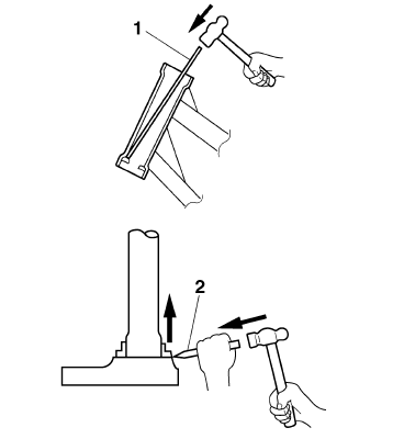
a. Remove the bearing races from the steering head pipe with a long rod "1" and hammer.
b. Remove the bearing race from the lower bracket with a floor chisel "2" and hammer.
c. Install a new dust seal and new bearing races.
| CAUTION: If the bearing races are not installed properly, the steering head pipe could be damaged. |
NOTE:
- Always replace the bearings and bearing races as a set.
- Whenever the steering head is disassembled, replace the dust seal.

4. Check:
- Upper bracket
- Lower bracket (along with the steering stem) Bends/cracks/damage →Replace.
 Removing the lower bracket
1. Stand the vehicle on a level surface.
WARNINGSecurely support the vehicle so that there
is
no danger of it falling over.
2. Remove:
Upper ring nut
Rubber washer
Lower r ...
 Installing the steering head
1. Lubricate:
Upper bearing
Lower bearing
Bearing races
2. Install:
Lower ring nut
Rubber washer
Upper ring nut
Lock washer
Refer to "CHECKING AND ADJUSTING
THE STEERING HEAD ...
Other materials:
Checking the rear shock absorber assembly
1. Check:
Rear shock absorber rod
Bends/damage Replace the rear
shock
absorber assembly.
Rear shock absorber
Oil leaks Replace the rear
shock absorber
assembly.
Spring
Damage/wear Replace the
rear shock absorber
assembly.
Bushing
Damage/wear Replace the rea ...
Cable routing
Front brake light switch lead
Right handlebar switch lead
Throttle cable
Main switch
Clutch cable
Clutch switch lead
Left handlebar switch lead
Sub-wire harness
Horn
Speed sensor lead
Front brake hose
Main switch lead
Left headlight assembly lead
Right headlight asse ...
Drive chain slack
The drive chain slack should be
checked before each ride and adjusted
if necessary.
To check the drive chain slack
Place the motorcycle on the sidestand.
TIP
When checking and adjusting the drive
chain slack, there should be no weight
on the motorcycle.
Shift the transmission in ...
