Yamaha YZF-R125 Service Manual: Setting the normal mode
NOTE:
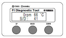
The engine speed, coolant temperature, and fault code, if detected, can be displayed on the LCD of the FI diagnostic tool when the tool is connected to the vehicle and is set to the normal mode.
1. Set the main switch to "OFF" and the engine stop switch to " ".
".
2. Disconnect the self-diagnosis signal connector "1", and then connect the FI diagnostic tool "2" as shown.
3. Set the main switch to "ON" and start the engine.
NOTE:
- The coolant temperature and engine speed appear on the LCD of the FI diagnostic tool.
- "POWER" LED (green) comes on.
- If a malfunction is detected in the system, the "WARNING" LED (orange) comes on.
4. Stop the engine.
NOTE:
If a malfunction is detected in the system, the fault code appears on the
LCD of the FI diagnostic tool
and the "WARNING" LED (orange) comes on.
5. Set the main switch to "OFF" to cancel the normal mode.
6. Disconnect the FI diagnostic tool and connect the self-diagnosis signal connector.
 Diagnostic mode
It is possible to monitor the sensor output data or check the activation of
actuators with the FI diagnostic
tool connected to the vehicle and set to the normal mode or the diagnostic
monitoring ...
 Setting the diagnostic mode
1. Set the main switch to "OFF" and the engine stop switch to "
".
2. Disconnect the self-diagnosis signal connector "1", and then connect the FI
diagnostic tool "2" as
shown.
3. Disconnect ...
Other materials:
Checking the cylinder and piston
1. Check:
Piston wall
Cylinder wall
Vertical scratches Replace the
cylinder,
and replace the piston and piston rings as a
set.
2. Measure:
Piston-to-cylinder clearance
a. Measure cylinder bore "C" with the cylinder
bore gauge.
NOTE:
Measure cylinder bore "C" by takin ...
Checking the shift drum assembly
1. Check:
Shift drum groove
Damage/scratches/wear Replace
the shift
drum assembly.
Shift drum segment "1"
Damage/wear Replace the
shift drum assembly.
Shift drum bearing "2"
Damage/pitting Replace the
shift drum assembly.
...
Assembling the front wheel
1. Install:
Wheel bearings
Oil seal
a. Install the new wheel bearings and oil seal in
the reverse order of disassembly.
CAUTION:Do not contact the wheel bearing inner
race
"1" or balls "2". Contact should be made
only with the outer race "3".
NOTE:
Use a socket " ...