Yamaha YZF-R125 Service Manual: Intake air pressure sensor
1. Check:
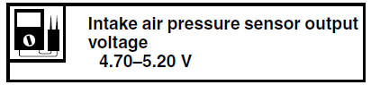
- Intake air pressure sensor output voltage
Out of specification Replace the throttle
body.
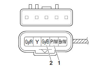
a. Connect the pocket tester (DC 20 V) to the
throttle body sensor assembly coupler as
shown.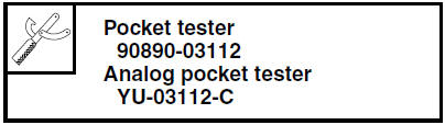
- Positive tester probe

pink/white "1" - Negative tester probe

gray/black "2"
b. Set the main switch to "ON".
c. Measure the intake air pressure sensor output voltage.
 Throttle position sensor
1. Check:
Throttle position sensor
a. Connect the digital circuit tester to the terminals
of the throttle body sensor assembly
coupler as shown.
Positive tester probe →
gray/red t ...
 Intake air temperature sensor
1. Check:
Intake air temperature sensor resistance
Out of specification Replace
the throttle
body.
a. Connect the pocket tester ( ×
1k) to the
throttle body sensor assembly co ...
Other materials:
Checking the fuel line
1. Remove:
Left side panel
Refer to "GENERAL CHASSIS" on page 4-1.
2. Lift the fuel tank. (Do not disconnect the fuel
hose, drain hose
3. Check:
Fuel hose "1"
Cracks/damage → Replace.
Loose connection Connect properly.
4. Install:
Fuel tank
Refer to "FUEL TANK" on pa ...
Checking the bulbs and bulb sockets
NOTE:
Do not check any of the lights that use LEDs.
Check each bulb and bulb socket for damage or
wear, proper connections, and also for continuity
between the terminals.
Damage/wear Repair or replace
the bulb,
bulb socket or both.
Improperly connected Properly
connect.
No c ...
Checking the fuel sender
1. Drain the fuel from the fuel tank.
2. Check:
Fuel sender resistance
Out of specification → Replace the fuel
sender.
a. Connect the pocket tester ( ×
10) to the fuel
sender coupler as shown.
Positive tester probe
sky blue "1"
Negative tester probe
orange/white " ...