Yamaha YZF-R125 Service Manual: Installing the relay arm
1. Lubricate:
- Spacers
- Bearings
- Oil seals
- Bolts (unthreaded shaft portion only)
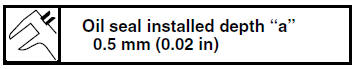
2. Install:
- Bearing "1" (to the relay arm)
- Oil seal "2"
(to the relay arm)
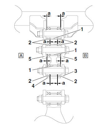
3. Rear shock absorber assembly
4. Relay arm
5. Connecting arm
A. Left side
B. Right side
 Checking the connecting arms and relay arm
1. Check:
Connecting arms
Relay arm
Damage/wear Replace.
2. Check:
Bearings
Oil seals
Damage/pitting Replace.
3. Check:
Spacers
Damage/scratches Replace.
...
 Installing the rear shock absorber assembly
1. Install:
Rear shock absorber assembly
Relay arm "1"
NOTE:
Install the relay arm as shown in the illustration.
2. Tighten:
Rear shock absorber assembly upper nut
Relay arm nu ...
Other materials:
Checking the clutch springs
The following procedure applies to all of the
clutch springs.
1. Check:
Clutch spring
Damage Replace the clutch
springs as a
set.
2. Measure:
Clutch spring free length "a"
Out of specification Replace
the clutch
springs as a set.
...
Faulty clutch
Clutch slips
1. Clutch
Improperly assembled clutch
Improperly adjusted clutch cable
Loose or fatigued clutch spring
Worn friction plate
Worn clutch plate
2. Engine oil
Incorrect oil level
Incorrect oil viscosity (low)
Deteriorated oil
Clutch drags
1. Clutch
Unevenly t ...
Checking the stator coil
1. Disconnect:
Stator coil coupler
(from the wire harness)
2. Check:
Stator coil resistance
Out of specification → Replace the
crankshaft
position sensor/stator assembly.
a. Connect the pocket tester ( ×
1) to the stator
coil coupler as shown.
b. Measure the sta ...