Yamaha YZF-R125 Service Manual: Ecu self-diagnostic function
The ECU is equipped with a self-diagnostic function in order to ensure that the fuel injection system is operating normally. If this function detects a malfunction in the system, it immediately operates the engine under substitute characteristics and illuminates the engine trouble warning light to alert the rider that a malfunction has occurred in the system. Once a malfunction has been detected, a fault code is stored in the memory of the ECU.
- To inform the rider that the fuel injection system is not functioning, the engine trouble warning light flashes when the start switch is being pushed to start the engine.
- If a malfunction is detected in the system by the self-diagnostic function, the ECU provides an appropriate substitute characteristic operation, and alerts the rider of the detected malfunction by illuminating the engine trouble warning light.
- After the engine has been stopped, the lowest fault code number is
indicated by the engine trouble
warning light (or displayed on the FI diagnostic tool). It remains stored in
the memory of the ECU until
it is deleted.
1. Engine trouble warning light
Engine trouble warning light fault code indication
Digit of 10: Cycles of 1 sec. on and 1.5 sec. off.
Digit of 1: Cycles of 0.5 sec. on and 0.5 sec. off.
Example: 42 
a. Light on
b. Light off
c. 1
d. 1.5
e. 0.5
f. 3
Engine trouble warning light indication and fuel injection system
operation 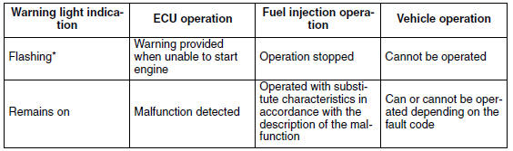
* The warning light flashes when any one of the conditions listed below is present and the start switch is pushed:
19: Blue/yellow ECU lead (broken or disconnected)
30: Lean angle sensor (latch up detected)
33: Faulty ignition
39: Fuel injector (open or short circuit)
41: Lean angle sensor (open or short circuit)
50: ECU internal malfunction (memory check error)
Checking the engine trouble warning light
The engine trouble warning light comes on for 3 seconds after the main switch
has been set to "ON". If
the warning light does not come on under these conditions, the warning light
(LED) may be defective.
a. Main switch "OFF"
b. Main switch "ON"
c. Engine trouble warning light off
d. Engine trouble warning light on for 3 seconds
 Circuit diagram
2. Crankshaft position sensor
4. Main fuse
5. Main switch
6. Radiator fan motor fuse
8. Sidestand switch
9. Battery
17.Engine stop switch
19.Intake air pressure sensor
20.Intake air temper ...
 Self-diagnostic function table
If the ECU detects an abnormal signal from a sensor while the vehicle is
being driven, the ECU illuminates
the engine trouble warning light and provides the engine with alternate
operating instru ...
Other materials:
Checking the primary drive gear
1. Remove:
Primary drive gear
Refer to "BALANCER GEAR" on page 5-53.
2. Check:
Primary drive gear
Damage/wear Replace the
primary drive
gear and clutch housing as a set.
Excessive noise during operation
Replace
the primary drive gear and clutch housing as
a set
...
Lubricating the drive chain
The drive chain consists of many interacting
parts. If the drive chain is not maintained properly,
it will wear out quickly. Therefore, the drive
chain should be serviced, especially when the
vehicle is used in dusty areas.
This vehicle has a drive chain with small rubber
O-rings between eac ...
Installing the crankshaft
1. Install:
Crankshaft "1"
NOTE:
Install the crankshaft with the crankshaft installer
pot "2", crankshaft installer bolt "3", adapter
(M12) "4" and spacer (crankshaft installer) "5".
CAUTION:To avoid scratching the crankshaft and to
ease the installation procedure, lubricate ...