Yamaha YZF-R125 Service Manual: Balancer gear
- Removing the primary drive gear and balancer gears
- Checking the balancer gears and primary drive gear
- Installing the primary drive gear and balancer gears
 Installing the shift shaft
1. Install:
Stopper lever "1"
Stopper lever spring "2"
NOTE:
Install the stopper lever spring as shown in the
illustration.
Hook the ends of the stopper lever spring onto
the stoppe ...
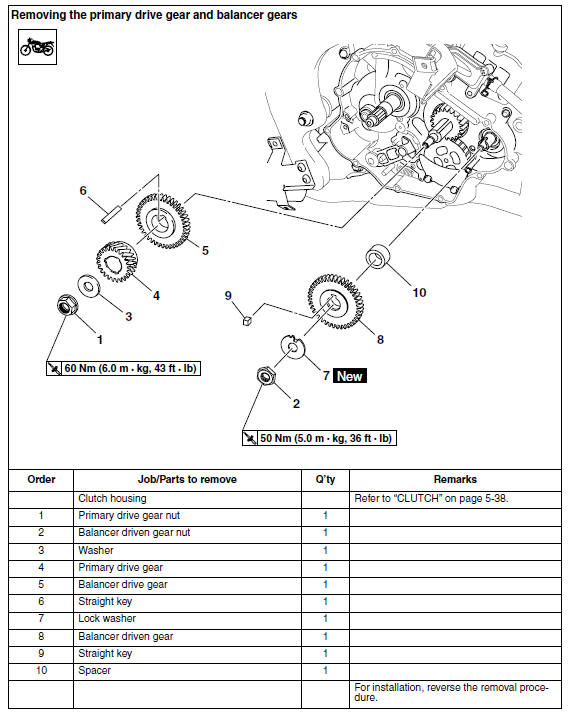
 Removing the primary drive gear and balancer gears
1. Loosen:
Primary drive gear nut "1"
NOTE:
Place the aluminum plate "a" between the balancer
drive gear "2" and the balancer driven
gear "3", and then loosen the primary drive gear
nut.
...
Other materials:
Removing the primary drive gear and balancer gears
1. Loosen:
Primary drive gear nut "1"
NOTE:
Place the aluminum plate "a" between the balancer
drive gear "2" and the balancer driven
gear "3", and then loosen the primary drive gear
nut.
2. Straighten the lock washer tab.
3. Loosen:
Balancer driven gear nut "1"
NOTE:
Place ...
Checking the rear brake master cylinder
1. Check:
Brake master cylinder
Damage/scratches/wear Replace.
Brake fluid delivery passages
(brake master cylinder body)
Obstruction Blow out with
compressed air.
2. Check:
Brake master cylinder kit
Damage/scratches/wear Replace.
3. Check:
Brake fluid reservoir
Cracks/ ...
Installing the starter clutch
1. Install:
Starter clutch assembly
Starter clutch bolts "1"
NOTE:
While holding the generator rotor "2" with the
sheave holder "3", tighten the starter clutch
bolts.
Do not allow the sheave holder to touch the
projection on the generator rotor.
Stake the end "a" of each start ...