Yamaha YZF-R125 Owners Manual: Rear wheel
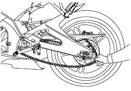
To remove the rear wheel
 WARNING
To avoid injury, securely support the
vehicle so there is no danger of it
falling over.
- Loosen the axle nut.
-
Axle nut
-
Drive chain slack adjusting bolt
-
Locknut
-
Brake caliper
- Lift the rear wheel off the ground according to the procedure.
- Remove the axle nut.
- Loosen the locknut on each side of the swingarm.
- Turn the drive chain slack adjusting bolts fully in direction (a) and push the wheel forward.
- Remove the drive chain from the rear sprocket.
TIP
If the drive chain is difficult to remove,
remove the wheel axle first,
and then lift the wheel upward
enough to remove the drive chain
from the rear sprocket.
The drive chain cannot be disassembled.
- While supporting the brake caliper bracket, pull the wheel axle out, and then remove the wheel. NOTICE: Do not apply the brake after the wheel has been removed together with the brake disc, otherwise the brake pads will be forced shut.
To install the rear wheel
- Install the wheel and the brake caliper bracket by inserting the wheel axle from the left-hand side.
TIP
- Make sure that the slot in the brake caliper bracket is fit over the retainer on the swingarm.
- Make sure that there is enough space between the brake pads before installing the wheel.
-
Retainer
-
Slot
- Install the drive chain onto the rear sprocket.
- Install the axle nut.
- Lower the rear wheel so that it is on the ground, and then put the sidestand down.
- Adjust the drive chain slack.
- Tighten the axle nut to the specified torque.
| Tightening torque: Axle nut: 85 Nm (8.5 m.kgf, 61 ft.lbf) |
 Front wheel
To remove the front wheel
WARNING
To avoid injury, securely support the
vehicle so there is no danger of it
falling over.
Loosen the front wheel axle pinch
bolt, then the wheel axle and ...
 Troubleshooting
Although Yamaha motorcycles receive
a thorough inspection before shipment
from the factory, trouble may occur during
operation. Any problem in the fuel,
compression, or ignition systems, for
...
Other materials:
Electrical components
1. Main switch
2. Clutch switch
3. Front brake light switch
4. Ignition coil
5. Throttle body sensor assembly (intake air
pressure sensor, intake air temperature
sensor, throttle position sensor)
6. FID (fast idle solenoid)
7. Rectifier/regulator
8. Lean angle sensor
9. Starting circui ...
Checking the ignition spark gap
1. Check:
Ignition spark gap
Out of specification Perform the
ignition
system troubleshooting, starting with step 5.
Refer to "TROUBLESHOOTING" on page
8-3.
NOTE:
If the ignition spark gap is within specification,
the ignition system circuit is operating normally.
a. Disconnect the spa ...
Removing the front wheel (disc)
1. Stand the vehicle on a level surface.
WARNINGSecurely support the vehicle so that there
is
no danger of it falling over.
2. Elevate:
Front wheel
NOTE:
Place the vehicle on a suitable stand so that the
front wheel is elevated.
3. Remove:
Front brake caliper
NO ...