Yamaha YZF-R125 Service Manual: Lubrication diagrams
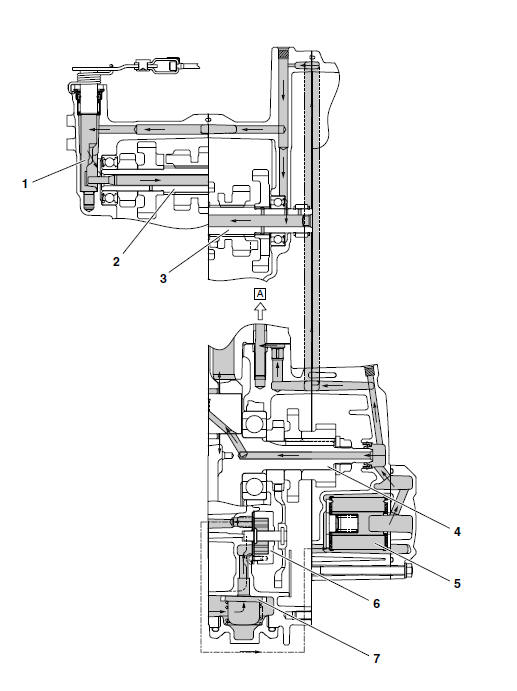
- Clutch push lever
- Main axle
- Drive axle
- Crankshaft
- Oil filter
- Oil pump assembly
- Oil strainer
- To cylinder head
- Camshaft
- Crankshaft
- Main axle
- Drive axle
 Engine oil lubrication chart
Oil pump
Oil filter element
Crankshaft
Camshaft
Main axle
Drive axle
...
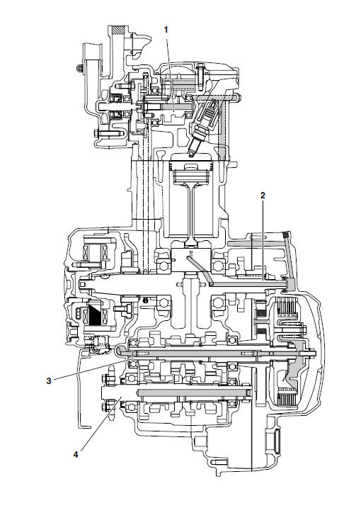
 Cooling system diagrams
Radiator inlet hose
Coolant reservoir hose
Radiator cap
Radiator
Coolant reservoir breather hose
Coolant reservoir
Water pump breather hose
Water pump
Radiator outlet hose
...
Other materials:
Disassembling the front fork legs
The following procedure applies to both of the
front fork legs.
1. Remove:
Rubber cap
Clip "1"
Front fork cap "2"
(with O-ring)
Fork spring
NOTE:
Push the front fork cap in the direction of the arrow
shown in the illustration to remove the clip.
2. Drain:
Fork oil
NOTE ...
Installing the shift forks and shift drum assembly
1. Install:
Shift fork-L "1"
Shift fork-C "2"
Shift fork-R "3"
Shift drum assembly "4"
Springs
Shift fork guide bar "5"
NOTE:
The embossed marks on the shift forks should
face towards the right side of the engine and be
in the following sequence: "R", "C", "L".
2. Check:
Tr ...
Checking the spark plug cap
1. Check:
Spark plug cap resistance
Out of specification Replace.
a. Remove the spark plug cap from the spark
plug lead.
b. Connect the pocket tester ( × 1k)
to the
spark plug cap as shown.
c. Measure the spark plug cap resistance. ...