Yamaha YZF-R125 Owners Manual: Ignition circuit cut-off system
The ignition circuit cut-off system (comprising the sidestand switch, clutch switch and neutral switch) has the following functions.
- It prevents starting when the transmission is in gear and the sidestand is up, but the clutch lever is not pulled.
- It prevents starting when the transmission is in gear and the clutch lever is pulled, but the sidestand is still down.
- It cuts the running engine when the transmission is in gear and the sidestand is moved down.
Periodically check the operation of the ignition circuit cut-off system according to the following procedure.
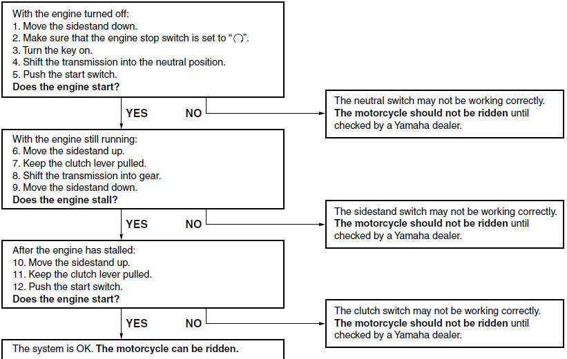
 WARNING
If a malfunction is noted, have a Yamaha
dealer check the system before riding.
 Sidestand
The sidestand is located on the left side
of the frame. Raise the sidestand or
lower it with your foot while holding the
vehicle upright.
TIP
The built-in sidestand switch is part of
the ign ...
 For your safety - pre-operation checks
Inspect your vehicle each time you use it to make sure the vehicle is in safe
operating condition. Always follow the inspection
and maintenance procedures and schedules described in the Owner's Ma ...
Other materials:
Checking the front fork
The condition and operation of the front
fork must be checked as follows at the
intervals specified in the periodic maintenance
and lubrication chart.
To check the condition
Check the inner tubes for scratches,
damage and excessive oil leakage.
To check the operation
Place the vehicle ...
Storage
Short-term
Always store your motorcycle in a cool,
dry place and, if necessary, protect it
against dust with a porous cover.
NOTICE
Storing the motorcycle in a
poorly ventilated room or covering
it with a tarp, while it is still
wet, will allow water and humidity
to seep in and ...
Checking the piston rings
1. Measure:
Piston ring side clearance
Out of specification Replace the
piston
and piston rings as a set.
NOTE:
Before measuring the piston ring side clearance,
eliminate any carbon deposits from the piston
ring grooves and piston rings.
2. Install:
Piston ring
(into the cylind ...