
Yamaha YZF-R125 Service Manual: Fuel tank
 Fuel system
...
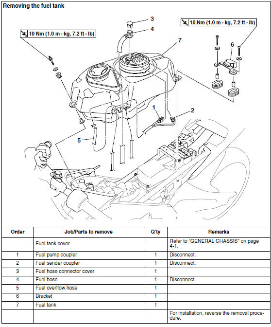
 Removing the fuel tank
1. Extract the fuel in the fuel tank through the
fuel tank filler hole with a pump.
2. Remove:
Fuel hose connector cover "1"
3. Disconnect:
Fuel hose "2"
CAUTION:
Be sure ...
Other materials:
Checking the valve seats
The following procedure applies to all of the
valves and valve seats.
1. Eliminate:
Carbon deposits
(from the valve face and valve seat)
2. Check:
Valve seat
Pitting/wear Replace the
cylinder head.
3. Measure:
Valve seat width C "a"
Out of specification Replace
the ...
Types of bulbs
The bulbs used on this vehicle are shown in the
illustration.
Bulbs "a" and "b" are used for the headlights
and usually use a bulb holder that must be detached
before removing the bulb. The majority
of these types of bulbs can be removed from
their respective socket by turning them coun ...
Electrical components
1. Main switch
2. Clutch switch
3. Front brake light switch
4. Ignition coil
5. Throttle body sensor assembly (intake air
pressure sensor, intake air temperature
sensor, throttle position sensor)
6. FID (fast idle solenoid)
7. Rectifier/regulator
8. Lean angle sensor
9. Starting circui ...