Yamaha YZF-R125 Owners Manual: Ignition circuit cut-off system
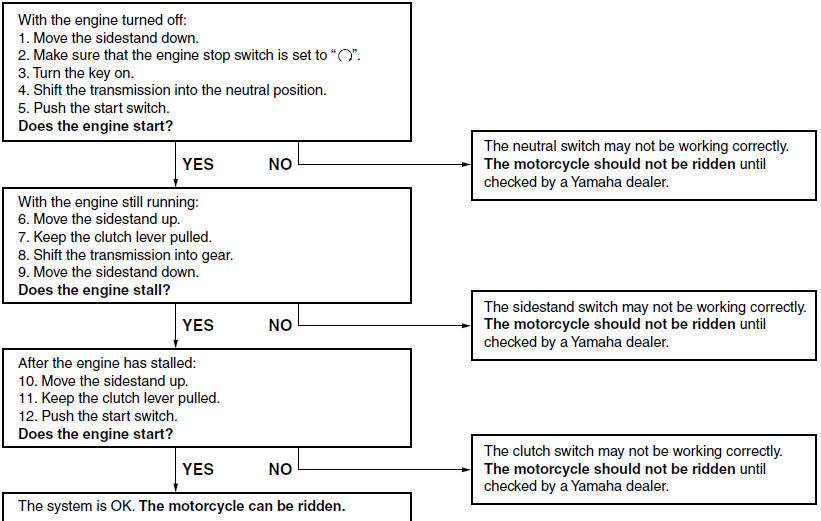
The ignition circuit cut-off system (comprising the sidestand switch, clutch switch and neutral switch) has the following functions.
- It prevents starting when the transmission is in gear and the sidestand is up, but the clutch lever is not pulled.
- It prevents starting when the transmission is in gear and the clutch lever is pulled, but the sidestand is still down.
- It cuts the running engine when the transmission is in gear and the sidestand is moved down.
Periodically check the operation of the ignition circuit cut-off system according to the following procedure.
 WARNING
If a malfunction is noted, have a Yamaha
dealer check the system before riding.
 Sidestand
The sidestand is located on the left side
of the frame. Raise the sidestand or
lower it with your foot while holding the
vehicle upright.
TIP
The built-in sidestand switch is part of
the ign ...
 For your safety - pre-operation checks
Inspect your vehicle each time you use it to make sure the vehicle is in safe
operating condition. Always follow the inspection
and maintenance procedures and schedules described in the Owner's Ma ...
Other materials:
Changing the coolant
1. Remove:
Lower side cowlings
Refer to "GENERAL CHASSIS" on page 4-1.
2. Remove:
Radiator cap "1"
WARNINGA hot radiator is under pressure.
Therefore,
do not remove the radiator cap when the engine
is hot. Scalding hot fluid and steam may
be blown out, which c ...
Indicator and warning lights
Indicator and warning lights
Neutral indicator light""
Turn signal indicator light""
High beam indicator light""
Engine trouble warning light""
Coolant temperature warning light""
Turn signal indicator light""
This indicator light flashes when the
turn signal switch is pushed t ...
Installing the steering head
1. Lubricate:
Upper bearing
Lower bearing
Bearing races
2. Install:
Lower ring nut
Rubber washer
Upper ring nut
Lock washer
Refer to "CHECKING AND ADJUSTING
THE STEERING HEAD" on page 3-22.
3. Install:
Upper bracket
Steering stem nut
NOTE:
Temporarily tighten t ...