
Yamaha YZF-R125 Service Manual: Troubleshooting
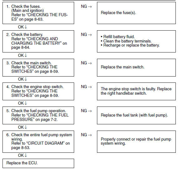
If the fuel pump fails to operate.
NOTE:
- Before troubleshooting, remove the following part(s):
1. Rider seat
2. Fuel tank
 Circuit diagram
4. Main fuse
5. Main switch
9. Battery
17.Engine stop switch
25.ECU (engine control unit)
30.Fuel pump
64.Ignition fuse ...
 Electrical components
1. Main switch
2. Clutch switch
3. Front brake light switch
4. Ignition coil
5. Throttle body sensor assembly (intake air
pressure sensor, intake air temperature
sensor, throttle position se ...
Other materials:
Catalytic converters
This vehicle is equipped with catalytic
converters in the exhaust system.
WARNING
The exhaust system is hot after operation.
To prevent a fire hazard or
burns:
Do not park the vehicle near
possible fire hazards such as
grass or other materials that
easily burn.
Park the vehic ...
Coolant
The coolant level should be checked
before each ride. In addition, the coolant
must be changed at the intervals
specified in the periodic maintenance
and lubrication chart.
To check the coolant level
Place the vehicle on a level surface
and hold it in an upright position.
TIP
...
Lubricating the drive chain
The drive chain consists of many interacting
parts. If the drive chain is not maintained properly,
it will wear out quickly. Therefore, the drive
chain should be serviced, especially when the
vehicle is used in dusty areas.
This vehicle has a drive chain with small rubber
O-rings between eac ...