Yamaha YZF-R125 Service Manual: Installing the shift arm
1. Install:
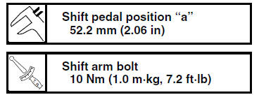
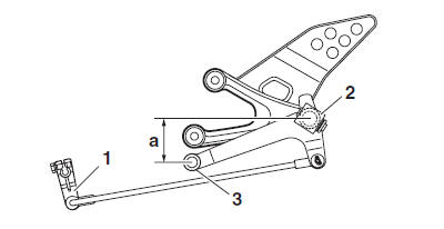
- Shift arm "1"
NOTE:
Make sure that the distance "a" between the
center of the left rider footrest "2" and the center
of the shift pedal "3" is within specification.
 Installing the engine
1. Install:
Engine "1"
Engine mounting bolt (rear lower side) "2"
Engine mounting nut (rear lower side) "3"
Engine mounting bolt (rear upper side) "4"
Engine mounting nut (rear upper side) ...
 Installing the exhaust assembly
1. Install:
Exhaust assembly "1"
Exhaust pipe nuts "2"
Exhaust assembly bolts "3" "4"
NOTE:
Do not fully tighten the nuts and bolts.
2. Tighten:
Exhaust pipe nuts "2"
Exhaust assem ...
Other materials:
Ecu self-diagnostic function
The ECU is equipped with a self-diagnostic function in order to ensure that
the fuel injection system is
operating normally. If this function detects a malfunction in the system, it
immediately operates the engine
under substitute characteristics and illuminates the engine trouble warning
li ...
Checking the timing chain and timing chain guide
1. Check:
Timing chain
Damage/stiffness Replace the
timing
chain and camshaft sprocket as a set.
2. Check:
Timing chain guide (intake side)
Damage/wear Replace.
Checking the oil strainer
1. Check:
Oil strainer
Damage Replace.
Contaminants Clean with solvent.
...
Catalytic converters
This vehicle is equipped with catalytic
converters in the exhaust system.
WARNING
The exhaust system is hot after operation.
To prevent a fire hazard or
burns:
Do not park the vehicle near
possible fire hazards such as
grass or other materials that
easily burn.
Park the vehic ...