Yamaha YZF-R125 Service Manual: General information
| NOTICE This manual was produced by MBK Industrie. primarily for use by Yamaha dealers and their qualified mechanics. It is not possible to include all the knowledge of a mechanic in one manual. Therefore, anyone who uses this book to perform maintenance and repairs on Yamaha vehicles should have a basic understanding of mechanics and the techniques to repair these types of vehicles. Repair and maintenance work attempted by anyone without this knowledge is likely to render the vehicle unsafe and unfit for use. Yamaha Motor Company, Ltd. is continually striving to improve all of its models. Modifications and significant changes in specifications or procedures will be forwarded to all authorized Yamaha dealers and will appear in future editions of this manual where applicable. |
NOTE:
Designs and specifications are subject to change without notice.
HOW TO USE THIS MANUAL
This manual is intended as a handy, easy-to-read reference book for the mechanic. Comprehensive explanations of all installation, removal, disassembly, assembly, repair and check procedures are laid out with the individual steps in sequential order.
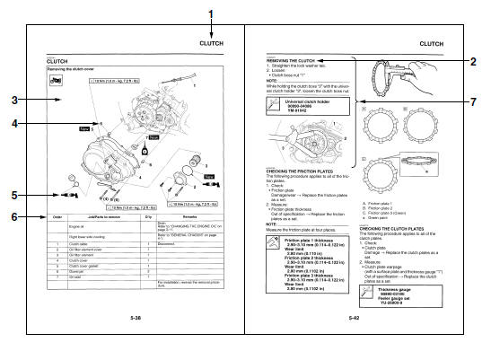
- The manual is divided into chapters and each chapter is divided into sections. The current section title "1" is shown at the top of each page.
- Sub-section titles "2" appear in smaller print than the section title.
- To help identify parts and clarify procedure steps, there are exploded diagrams "3" at the start of each removal and disassembly section.
- Numbers "4" are given in the order of the jobs in the exploded diagram. A number indicates a disassembly step.
- Symbols "5" indicate parts to be lubricated or replaced.
Refer to "SYMBOLS".
- A job instruction chart "6" accompanies the exploded diagram, providing the order of jobs, names of parts, notes in jobs, etc.
- Jobs "7" requiring more information (such as special tools and technical data) are described sequentially.
SYMBOLS
The following symbols are used in this manual for easier understanding.
NOTE:
The following symbols are not relevant to every vehicle.
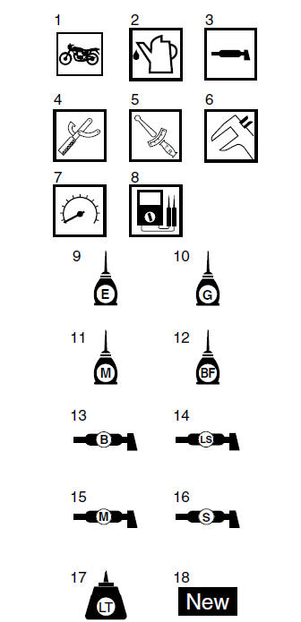
1. Serviceable with engine mounted
2. Filling fluid
3. Lubricant
4. Special tool
5. Tightening torque
6. Wear limit, clearance
7. Engine speed
8. Electrical data
9. Engine oil
10.Gear oil
11.Molybdenum disulfide oil
12.Brake fluid
13.Wheel bearing grease
14.Lithium-soap-based grease
15.Molybdenum disulfide grease
16. Silicone grease
17.Apply locking agent (LOCTITE).
18.Replace the part with a new one.
- Identification
- Features
- Important information
- Preparation for removal and disassembly
- Replacement parts
- Gaskets, oil seals and o-rings
- Lock washers/plates and cotter pins
- Bearings and oil seals
- Circlips
- Checking the connections
- Special tools

 Identification
Vehicle identification number
The vehicle identification number "1" is stamped
into the right side of the steering head pipe.
Model label
The model label "1" is affixed to the frame. This
inf ...
Other materials:
Parking
When parking, stop the engine, and
then remove the key from the main
switch.
WARNING
Since the engine and exhaust
system can become very hot,
park in a place where pedestrians
or children are not likely to
touch them and be burned.
Do not park on a slope or on soft
ground, ...
Assembling the crankcase
1. Thoroughly clean all the gasket mating surfaces
and crankcase mating surfaces.
2. Apply:
Sealant
(onto the crankcase mating surfaces)
NOTE:
Do not allow any sealant to come into contact
with the oil gallery.
3. Install:
Right crankcase
NOTE:
Turn the shift drum segment ...
Removing the rear brake master cylinder
NOTE:
Before removing the rear brake master cylinder,
drain the brake fluid from the entire brake system.
1. Disconnect:
Rear brake light switch coupler
2. Loosen:
Rear brake light switch "1"
3. Remove:
Rear brake master cylinder bolts
Rear brake master cylinder
4. Remove:
...