Yamaha YZF-R125 Service Manual: Circuit diagram
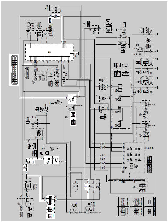
4. Main fuse
5. Main switch
9. Battery
17.Engine stop switch
25.ECU (engine control unit)
30.Fuel pump
64.Ignition fuse
 Fuel pump system
...
 Troubleshooting
If the fuel pump fails to operate.
NOTE:
Before troubleshooting, remove the following part(s):
1. Rider seat
2. Fuel tank
...
Other materials:
Checking the rocker arms and rocker arm shafts
The following procedure applies to all of the
rocker arms and rocker arm shafts.
1. Check:
Rocker arm
Damage/wear Replace.
2. Check:
Rocker arm shaft
Blue discoloration/excessive wear/pitting/
scratches Replace or
check the lubrication
system.
3. Measure:
Rocke ...
Starting circuit cut-off system operation
If the engine stop switch is set to "
" and the main switch is set to
"ON" (both switches are closed), the
starter motor can only operate if at least one of the following conditions is
met:
The transmission is in neutral (the neutral switch is closed).
The clutch lever is pulled to the ...
General tightening torque specifications
This chart specifies tightening torques for standard
fasteners with a standard ISO thread pitch.
Tightening torque specifications for special components
or assemblies are provided for each
chapter of this manual. To avoid warpage, tighten
multi-fastener assemblies in a crisscross pattern
and ...