Yamaha YZF-R125 Service Manual: Checking the switches
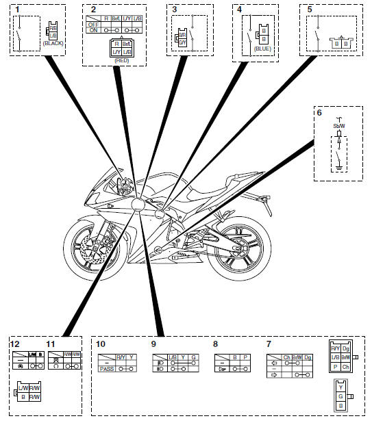
1. Clutch switch
2. Main switch
3. Front brake light switch
4. Sidestand switch
5. Rear brake light switch
6. Neutral switch
7. Turn signal switch
8. Horn switch
9. Dimmer switch
10.Pass switch
11.Engine stop switch
12.Start switch
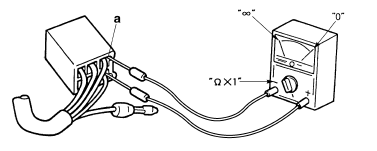
Check each switch for continuity with the pocket tester. If the continuity reading is incorrect, check the wiring connections and, if necessary, replace the switch.
| CAUTION: Never insert the tester probes into the
coupler terminal slots "a". Always insert the probes from
the opposite end of the coupler, taking care not to loosen or damage the
leads. |

NOTE:
- Before checking for continuity, set the pocket tester to "0" and to the " × 1" range.
- When checking for continuity, switch back and forth between the switch positions a few times.
The switches and their terminal connections are illustrated as in the following example of the main switch.
The switch positions "a" are shown in the far left column and the switch lead colors "b" are shown in the top row.
The continuity (i. e., a closed circuit) between switch terminals at a given
switch position is indicated by
"  ". There is continuity between
red and brown/blue, and blue/yellow and blue/black when the
switch is set to "ON".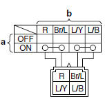
 Electrical components
1. Main switch
2. Clutch switch
3. Front brake light switch
4. Ignition coil
5. Throttle body sensor assembly (intake air
pressure sensor, intake air temperature
sensor, throttle position se ...
 Checking the bulbs and bulb sockets
NOTE:
Do not check any of the lights that use LEDs.
Check each bulb and bulb socket for damage or
wear, proper connections, and also for continuity
between the terminals.
Damage/wear Repa ...
Other materials:
Checking the friction plates
The following procedure applies to all of the friction
plates.
1. Check:
Friction plate
Damage/wear Replace the
friction plates
as a set.
2. Measure:
Friction plate thickness
Out of specification Replace
the friction
plates as a set.
NOTE:
Measure the friction plate ...
Checking the bulbs and bulb sockets
NOTE:
Do not check any of the lights that use LEDs.
Check each bulb and bulb socket for damage or
wear, proper connections, and also for continuity
between the terminals.
Damage/wear Repair or replace
the bulb,
bulb socket or both.
Improperly connected Properly
connect.
No c ...
Installing the clutch
1. Install:
Conical spring washer "1"
NOTE:
Install the conical spring washer as shown in the
illustration.
2. Install:
Clutch housing
Thrust washer "1"
NOTE:
Be sure to install the thrust washer so that its
sharp edge "a" is facing away from the clutch
boss.
3. Instal ...