Yamaha YZF-R125 Service Manual: Adjusting the valve clearance
The following procedure applies to all of the valves.
NOTE:
- Valve clearance adjustment should be made on a cold engine, at room temperature.
- When the valve clearance is to be measured or adjusted, the piston must be at top dead center (TDC) on the compression stroke.
1. Remove:
- Bottom cowling Refer to "GENERAL CHASSIS" on page 4-1.
- Fuel tank Refer to "FUEL TANK" on page 7-1.
2. Disconnect:
- Spark plug cap
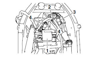
3. Remove:
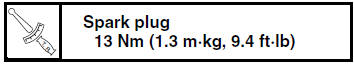
- Spark plug
- Ignition coil "1"
- Plastic locking tie "2"
4. Disconnect:
- Main switch coupler "3"
- Left handlebar switch couplers "4"
- Cylinder head cover
- Cylinder head cover gasket Refer to "CYLINDER HEAD" on page 5-7.
NOTE:
When removing the cylinder head cover, lift it out from between the frame tubes.
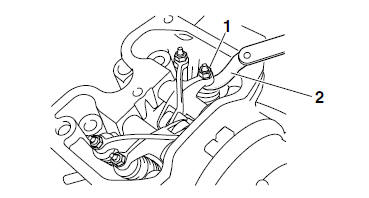
5. Remove:
- Timing mark accessing screw "1"
- Crankshaft end accessing screw "2"
6. Measure:
- Valve clearance
Out of specification → Adjust.
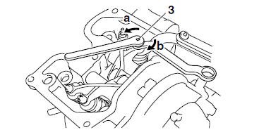
a. Turn the crankshaft counterclockwise.
b. Align the TDC mark "a" on the generator rotor with the stationary pointer "b" on the generator cover.
c. Check that the cam lobes are positioned as shown in the illustration.
d. Measure the valve clearance with a thickness gauge "1".
Out of specification → Adjust.
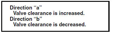
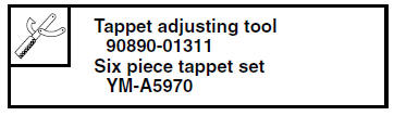
7. Adjust: - Valve clearance
a. Loosen the locknut "1".
b. Insert a thickness gauge "2" between the end of the adjusting screw and the valve tip.
c. Turn the adjusting screw "3" in direction "a" or "b" until the specified valve clearance is obtained.
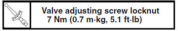
- Hold the adjusting screw to prevent it from
moving and tighten the locknut to specification.
d. Measure the valve clearance again.
e. If the valve clearance is still out of specification, repeat all of the valve clearance adjustment steps until the specified clearance is obtained.
8. Install:
- Crankshaft end accessing screw (along with the O-ring
 )
) - Timing mark accessing screw
(along with the O-ring
 )
)
9. Install:
- Cylinder head cover gasket

- Cylinder head cover
- Spark plug Refer to "CYLINDER HEAD" on page 5-7.
10.Connect:
- Left handlebar switch couplers "1"
- Main switch coupler "2"
11.Install:
- Plastic locking tie "3"

NOTE:
Fasten the wire harness (to horn), wire harness (to left handlebar switch), front brake light switch lead, right handlebar switch lead, and main switch lead to the frame with a plastic locking tie.
Refer to "CABLE ROUTING" on page 2-33.
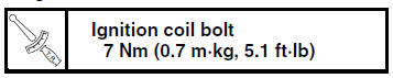
12.Install:
- Ignition coil "4"
- Spark plug

13.Connect:
- Spark plug cap
14.Install:
- Fuel tank Refer to "FUEL TANK" on page 7-1.
- Bottom cowling Refer to "GENERAL CHASSIS" on page 4-1.
 Engine
...
 Adjusting the exhaust gas volume
NOTE:
Be sure to set the CO density level to standard,
and then adjust the exhaust gas volume.
1. Remove:
Rider seat
Refer to "GENERAL CHASSIS" on page 4-1.
2. Set the main switch to "OFF" ...
Other materials:
Removing the front fork legs
The following procedure applies to both of the
front fork legs.
1. Stand the vehicle on a level surface.
WARNINGSecurely support the vehicle so that there
is
no danger of it falling over.
2. Loosen:
Handlebar pinch bolt "1"
Handlebar bolt "2"
Upper bracket ...
Checking the clutch boss
1. Check:
Clutch boss splines
Damage/pitting/wear Replace the
clutch
boss.
NOTE:
Pitting on the clutch boss splines will cause erratic
clutch operation.
Checking the pressure plate
1. Check:
Pressure plate
Cracks/damage Replace.
Checking the clutch push lever and short clutch push ...
Checking the clutch springs
The following procedure applies to all of the
clutch springs.
1. Check:
Clutch spring
Damage Replace the clutch
springs as a
set.
2. Measure:
Clutch spring free length "a"
Out of specification Replace
the clutch
springs as a set.
...